DIY Reflow Plate
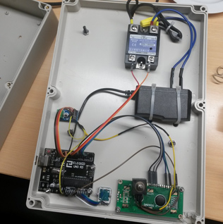
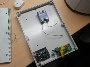
 Here's everything wired up.
For the most part I was able to make due with point to point connections. But I had to make a 4 way splice in the 5v positive wire (yellow).
I forgot to provide power for the Arduino, so I added a wall wart in there.
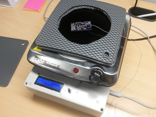
 And here it is all assembled (and programmed).
I thought the system might work better with a cover over the boards, so I bought some thick silicone pot holders from amazon to act as spacers. A piece of glass goes on top.
 I use this piece of "glass" as a cover. It's actually transparent ceramic, which is highly resistant to thermal shock.
I started with a piece of plain old window glass, and it worked great.. until it exploded and blasted glass all over my office. I didn't get a pic unfortunately.
I bought the ceramic square from McMaster Carr.
 Here's the reflow profile I'm using.
Opinions vary on the how this profile should look exactly but it's always a series of ramp and soak steps like this.
I tried PID control at first, but it didn't work very well. Like most temperature feedback, it's quite laggy which causes extreme overshoot. Maybe that could have been fixed with tuning, but I found a better way. It's useful for a lot things so I'll explain how it works.
 What you do is pick 2 duty cycles, 1 that produces a ramp rate somewhat lower than the target, and another that produces a ramp greater than the target. Then you use simple bang-bang control to switch between them. Because the temperature rises and falls at a much slower rate the over and undershoot are dramatically reduced. The cycling is also slower, and the system spends more time inside the deadband. I call this "Modified Bang-Bang Control".
To reduce overshoot further, I added a secondary control function, which cuts off the heat early and allows the temp to "coast" up to the target.


